03Concept design · Active implant
Optogenetic touch-restoration implant
Timed 470 nm light on light-sensitive touch receptors after burn injury, from a titanium implant that charges through the skin.
Coursework concept · Not built or tested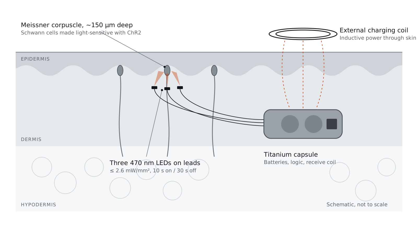
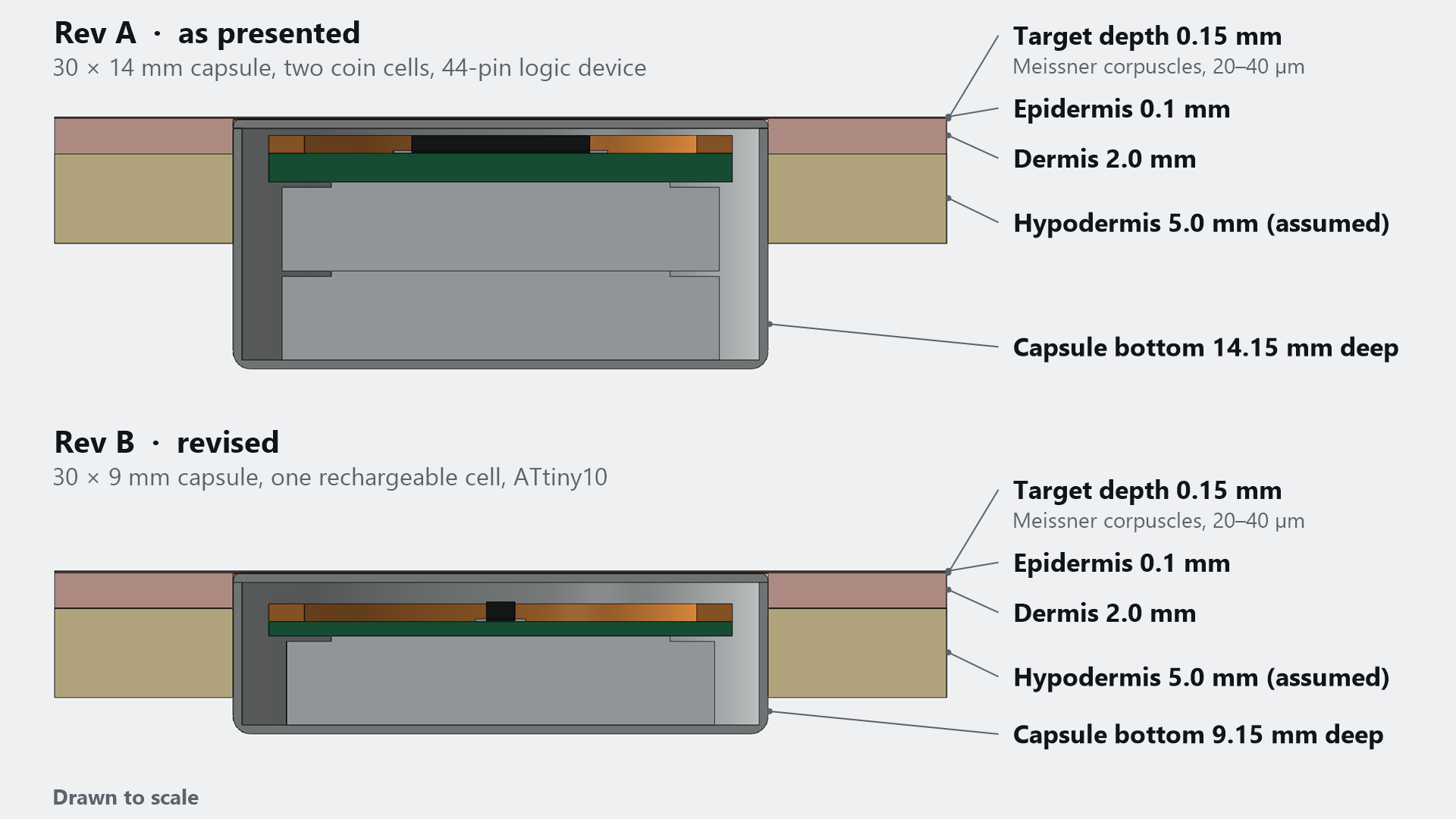
After the team's cross-section figure. Schematic, not to scale: at true scale the 3 cm capsule is 200 times the 150 µm target depth.
- Course
- BME 250, University of Illinois Chicago
- Timeline
- Fall 2025 · about 5 weeks
- Team
- 4 students
- My part
- Test requirements: heat, power, size, durability, long-term placement
01Problem
Partial-thickness burns damage the nerve endings that turn touch into signals. Those nerves regrow poorly, so patients lose touch or feel nerve pain instead. Optogenetics can make nerves fire with light, but a clinical implant has to aim light at tiny targets, last in the body and power itself.
02Requirements and constraints
The target is the Meissner corpuscle, a touch receptor about 150 µm deep and 20–40 µm wide. The implant must seal its electronics, sit where it spares healthy nerves and vessels, and keep charging fields within tissue limits. Verifiable requirements are in the table.
| Requirement | Verification | Status |
|---|---|---|
| LED intensity at most 2.6 mW/mm² | Planned: calculation. Better: optical power meter over the LED’s emitting area | Not run |
| Open-loop timing: 10 s of light, then 30 s off | Standard test case on the timing code | Not run |
| Outer surface no more than 2 °C above 37 °C (added after review) | Thermocouple on the capsule and LEDs in a 37 °C tissue phantom, over full cycles | Proposed |
03Design decisions and why
- 01Put a light-gated channel at the receptor.
- Schwann cells in Meissner corpuscles help set when touch signals fire. Expressing channelrhodopsin-2 (ChR2) lets 470 nm light depolarize them; in mice, this drove nerve firing within 100 ms of light onset.
- 02Open loop first.
- A closed loop needs sensors and processing and adds feedback delay, so we chose a fixed timer and listed closed loop as future work.
- 03Size the circuit.
- Three 470 nm LEDs run at 2.9 V and 5 mA, so a 20 Ω resistor sets the current from a 3 V supply: (3.0 − 2.9) V ÷ 5 mA. A programmable logic device times the cycle.
- 04Seal everything but the light.
- Batteries and logic sit in a titanium capsule with the LEDs outside; inductive charging avoids battery-replacement surgery.
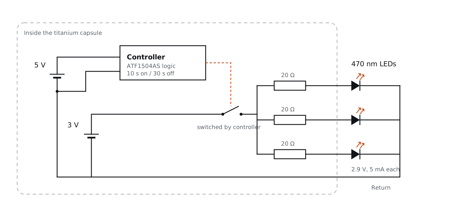
04What I did
I defined the test requirements for heat generation, power, device size, durability and long-term placement. I turned the safety review (heating, electrical isolation, biocompatibility, placement depth and charging exposure) into checks that could be run. I also modeled the implant in SOLIDWORKS 2025 (see CAD).
05Outcome and limits
A concept report and a circuit design; nothing was built or tested. We judged the 3 cm implant too large. Durability, aiming at 150 µm targets, natural-feeling sensation and sparing pain fibers remain open, and delivering ChR2 to human cells is unsolved.
06What I’d do next
- Swap the logic device for the ATtiny10 from our early notes, a 6-pin microcontroller with its own timer that runs on 1.8–5.5 V, so one cell powers everything.
- Use a rechargeable cell and a constant-current LED driver: with 0.1 V of headroom, the LEDs go dark once the cell sags to 2.9 V.
- Replace the unsourced “25 °C” heat figure with the ISO 14708-1 limit (surface ≤ 2 °C above body temperature), tested in a 37 °C phantom.
07Engineering checks
| Quantity | Value |
|---|---|
| Current while lit, 3 × 5 mA | 15 mA |
| Duty cycle, 10 s of every 40 s | 25% |
| Average current | 3.75 mA |
| Runtime, 300 mAh as in the report | 80 h |
| Runtime, CR2450 (620 mAh, not rechargeable) | 165 h |
| Runtime per charge, LIR2450 (120 mAh, rechargeable) | 32 h |
The CR2450 named in our notes is a primary lithium cell, so it cannot use the inductive charger, and its datasheet rates it for 0.2 mA continuous drain against the 15 mA drawn while lit. With a 20 Ω resistor and a 2.9 V LED, current falls from 5 mA at 3.0 V to zero at 2.9 V, so light output depends on cell voltage. A constant-current driver removes that dependence.
| Property | ATF1504ASV (linked in our slides) | ATtiny10 (early notes) |
|---|---|---|
| Type | Programmable logic (CPLD), 64 macrocells | 8-bit microcontroller |
| Package | 44-lead TQFP | 6-pin SOT-23 |
| Supply | 3.0–3.6 V | 1.8–5.5 V |
| Time base | External clock needed | Internal oscillator and watchdog timer |
| Lowest standby | 5 µA (ASVL version) | < 0.1 µA power-down |
08CAD
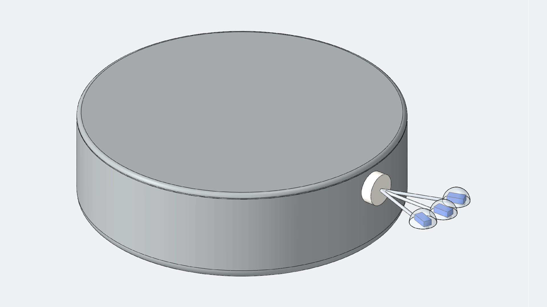
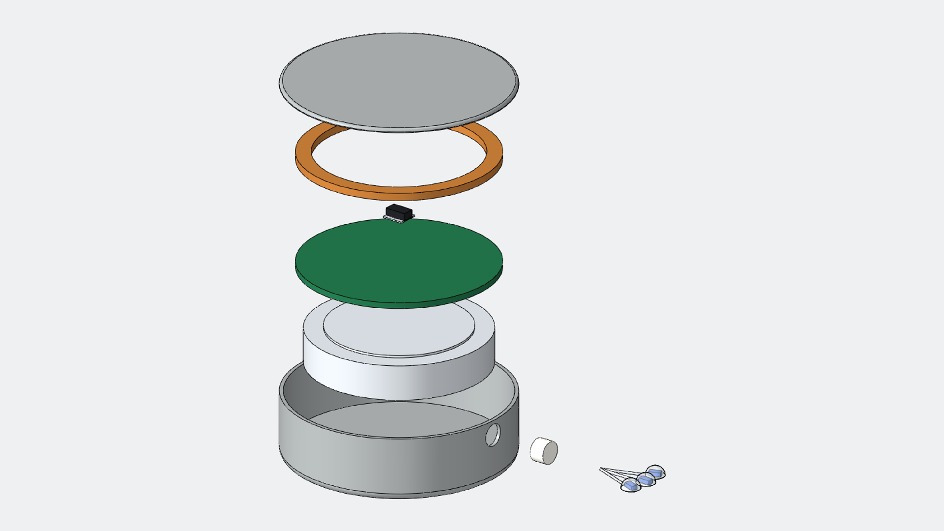
My SOLIDWORKS 2025 model of the capsule, cells, board, coil, controller and LED leads, in two configurations: as presented (two cells, 44-pin logic) and revised (one rechargeable cell, ATtiny10). The section is to scale. With its top at the 0.15 mm target depth, the 14 mm capsule reaches 14.15 mm deep, about twice the 7.1 mm of skin modeled. The revised 9 mm capsule still reaches 9.15 mm.
Sources
Show all 10 sources
Cited in the course report
- Tsolakidis S et al. “Out of touch”: recovering sensibility after burn injury, a review of the literature. European Burn Journal 3(2), 32 (2022). mdpi.com
- Piccinin MA. Histology, Meissner corpuscle. StatPearls (2023). NBK518980
- Ojeda-Alonso J et al. Sensory Schwann cells set perceptual thresholds for touch and selectively regulate mechanical nociception. Nat Commun 15, 898 (2024). doi:10.1038/s41467-024-44845-8. The course report attributed this title to a different 2019 paper; corrected here.
- Cambridge Consultants. Wireless charging: powering the future for implantable medical devices (2021). cambridgeconsultants.com
Post-project review
- Microchip. ATF1504ASV(L) 3.3 V 64-macrocell CPLD data sheet. microchip.com
- Microchip. ATtiny10 product page and data sheet. microchip.com
- Panasonic. CR2450 lithium coin cell datasheet (3 V, 620 mAh, 24.5 × 5.0 mm). panasonic.com
- Multicomp. LIR2450 rechargeable lithium-ion coin cell (3.6 V, 120 mAh). farnell.com
- ISO 14708-1:2014. Implants for surgery, active implantable medical devices, part 1 (outer surface ≤ 2 °C above body temperature). iso.org
- Owen SF, Liu MH, Kreitzer AC. Thermal constraints on in vivo optogenetic manipulations. Nat Neurosci 22, 1061–1065 (2019). doi:10.1038/s41593-019-0426-z